Appendix F - Answers You Should Know Regarding GeoSWMM 2D Modeling
- How to name the project geodatabase or directory path in GeoSWMM?
Naming the GeoSWMM project or directory path while preparing or creating 1D or 2D models, users need to follow few rules. Such as:
-
Try to avoid space, special characters and long pathname.
-
Always start with a letter and keep the file name between 10 to 14 character.
-
Use underscore ( _ ) in between words for the folder name with more than one word.
-
Terms that may conflict with SQL or other language’s reserved words need avoid. For example: OBJECTID, VALUE, COUNT, OR, ON, NOT, IN, OVER, SELECT etc.
- Can users migrate back to 1D model once they create 2D model with GeoSWMM 2D?
No. There is no going back to the 1D model once the 2D model is created. In case of users wanting access to the previous 1D version of the 2D model, they can keep a copy of the 1D model using “Save A Copy” command and then run the 2D operation.
- Is there any necessity to remain the boundary extent where cell depth is zero?
No. As 2D cell depth zero means water did not flow on those areas. User can shrink the boundary from at such places. The boundary needs to increase where 2D cell max depth is high near the boundary. Boundary need to increase in the direction where water depth is high to get the actual extent of the water flow. Boundary layer need to update in this case which can be done using “Define Boundary Layer” tool.
- Why must surcharge depth be assigned in 1D nodes?
By assigning surcharge depth, it is made sure that the flow exceeding maximum depth of a node reaches the 2D floodplain through orifice. If surcharge depth is not assigned, then the excessive flow will not flow through the orifice and will be considered as flood loss. Surcharge depth is the depth above the maximum depth of any junction. While connecting control structure like orifice/weir with regular node/ junction, it is relevant to define both maximum depth and surcharge depth of that junction for the orifice. Flood loss will be accounted only if the head of that node crosses the summation of maximum depth and surcharge depth. The value of the surcharge depth should be assigned same as the depth/height of orifice – for 2D flood model. Users do not need to populate this attribute because in this case it will be assigned 40 ft. or 12 m by default while creating 2D features. However, user might need to update the values manually if default values are inadequate.
- What steps are involved when flood boundary exceeds the watershed boundary?
Generate an outfall there to drain out the water properly.
- What factors need to be considered when tuning orifice width in full flow condition?
If there is a need to increase width later on, it should be calculated based on parameters such as orifice inlet and outlet node max depth. The best approach is to assign a width either the same width of the 2D conduit or same the grid resolution. If that doesn't work, further increase may be required based on results from inlet nodes.
- What will happen to the sub catchment outlet as all the irregular channels and their corresponding nodes have been remained inactive?
The 1D node that represents the sub catchment outlet will be kept and connected with 2D feature. All the irregular channels and corresponding nodes will be kept inactive except for the sub catchment outlets. These nodes will be kept active so that flow accumulating in these nodes can be conveyed to 2D flood plain through 1D-2D connection.
- Can 1D node connect with 2D node in GeoSWMM 2D, if 1D node falls inside the obstruction layer or outside the boundary layer?
No. GeoSWMM 2D tools will only connect with the 1D junction which are inside the boundary layer and outside of obstruction layer. However, users can always connect the 1D junction to 2D junction manually according to project objectives.
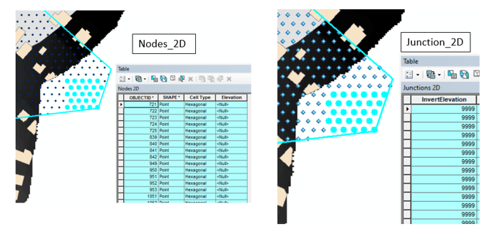
- What does it mean by 9999 values in the 2D layer attribute?
There could be two possible scenarios where 9999 values will be returned in the 2D layers attribute:
-
DEM no data values
-
Boundary layer extent outside of DEM
In both cases, null values will be assigned to elevation field in the Nodes_2D layer. Continuing with those layers, the invert elevation and offset calculations for 2D layers and the 1D-2D connection layer will return default values such as 9999 respectively.
It is recommended to use a valid DEM data layer or update the boundary layer considering DEM extent. (will update)

