Drag-and-Drop System Model Builder
It's very common that the urban or municipal authorities have their own Stormwater network information. GeoSWMM provides an enhanced option for SWMM network model preparation if those datasets are available in GIS. Rather than starting from scratch, hydrologic models are often created from a readily available network dataset. Most water or environment utilities information is managed in a GIS database.
The Drag-and-drop System Model Builder in GeoSWMM is a very specialized feature for easy, quick, and accurate preparation of a SWMM network model. It extracts model information directly from the external GIS data source and assigns it to the model components. Using this feature may be very useful in cases when the user has their Stormwater data source in GIS layers or from another SWMM project.
In the drag-and-drop system, the user needs to create an empty and new GeoSWMM project geodatabase. At the same time, source data layers for SWMM components (e.g. subcatchments, nodes, links) need to be present in the same working ArcGIS Pro interface. Next, the individual item layer is selected in the TOC, dragged with the cursor, and dropped over the corresponding item in the GeoSWMM Object Panel. When dragged-and-dropped, the property mapping window appears, where the user can assign the required parameters from the source data layer fields for any SWMM visual object (e.g. subcatchments). The entire process is briefly illustrated in the following section for *Subcatchments *import using this method.
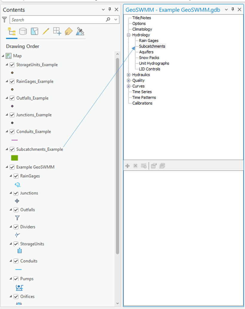
- In ArcGIS Pro map table of contents, select the shape file- Subcatchment. Press the left button of the mouse on it and hold. Then drag it to the Model Object Panel and release it over the object- Subcatchments.

Fig 61: Drag-and-drop process in GeoSWMM
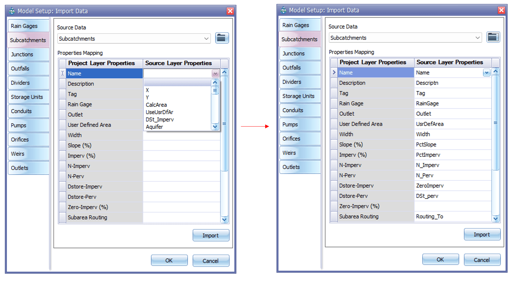
- An attribute mapping window will appear as follows. Assign the property fields appropriately in this window. Then Click OK to accept the changes made and exit from the window. Note that you must assign the Name field. Other properties are optional. If not assigned, then the program-default values will be assigned automatically.

Fig 62: Attribute mapping windows in GeoSWMM
-
Click on Import button to add the external layer into the GeoSWMM project layer along with the mapped attributes/properties.
-
Follow steps 1-2 similarly for objects- Rain Gages, Junctions, Outfalls and Conduits. You can map the layer attributes in any order. While mapping subcatchment and conduit properties, you can assign custom area and length entries respectively, by specifying User Defined Area and User Defined Length fields. If these fields are not specified, GeoSWMM will automatically calculate the subcatchment areas and conduit lengths using the ArcGIS Pro map projection information.
-
Click on OK button to complete the importing process. The model network is already developed. After the mapping is complete, click on the Save (
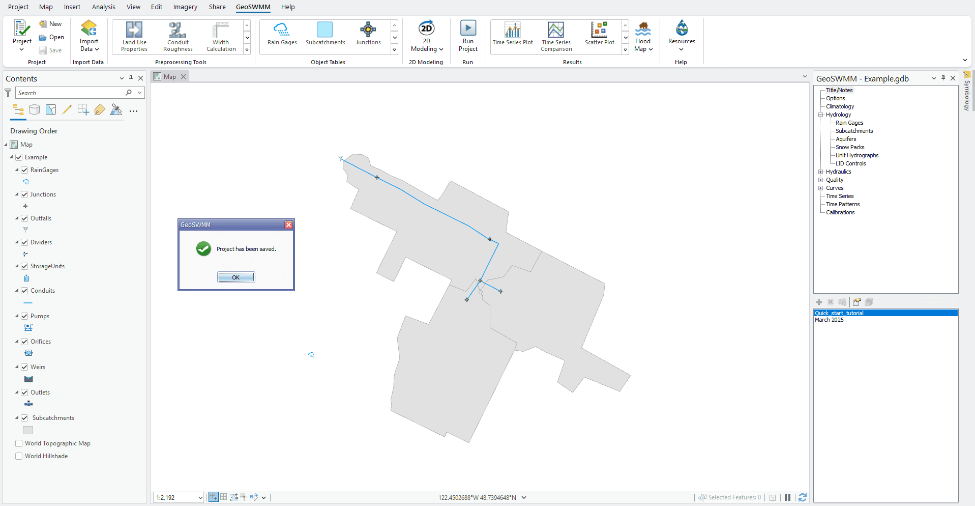
) button on GeoSWMM toolbar. The project will be saved and show you a notification message like the following figure. Click OK to accept.

Fig 63: Project Save notification
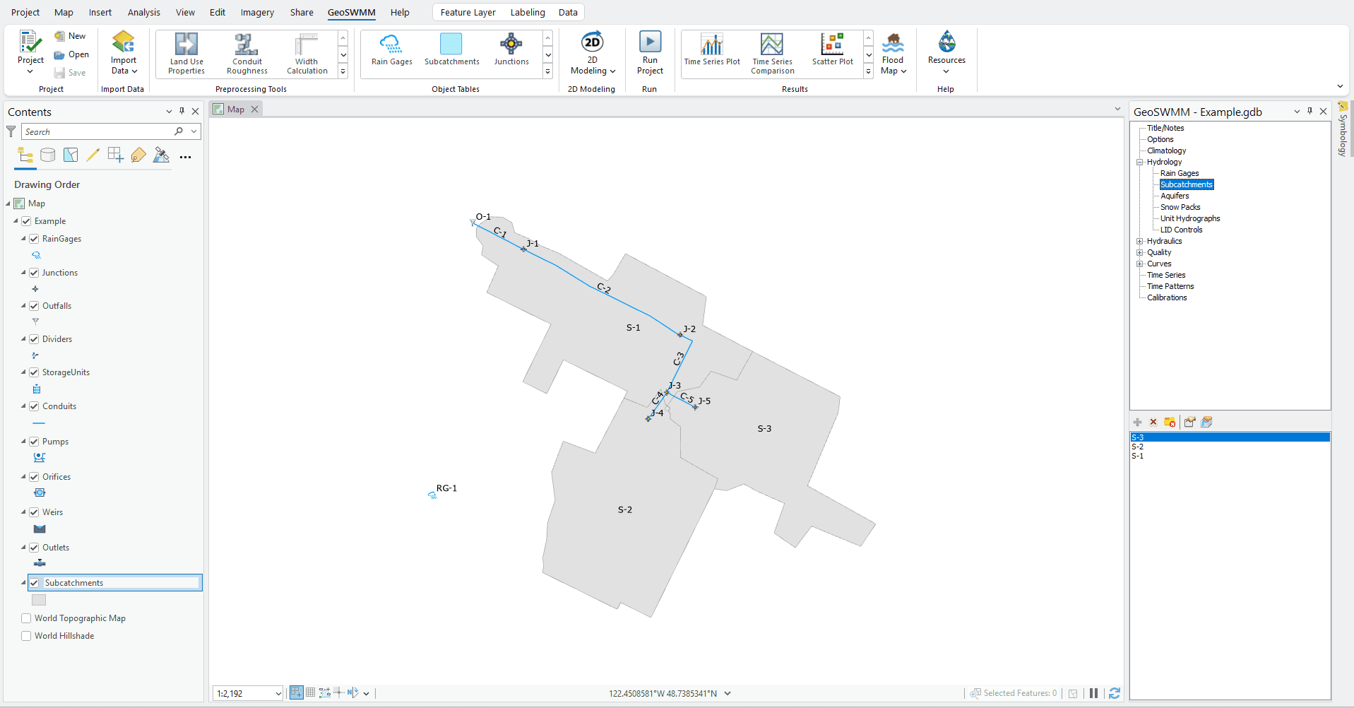
- Notice that the geodatabase shows its layers with program-default symbology. However, you can also use the object symbology properties from the supplied layer (.lyrx) files. Uncheck/ remove the shape files in the table of contents. Now the ArcGIS Pro map window will display only the model geodatabase features. The Model Object Panel also shows a list of objects under each network item. Model network building is complete. Now label the object feature classes as shown below.

Fig 64: GeoSWMM model network
