GeoSWMM Additional Features
Use and Manage Interface Files
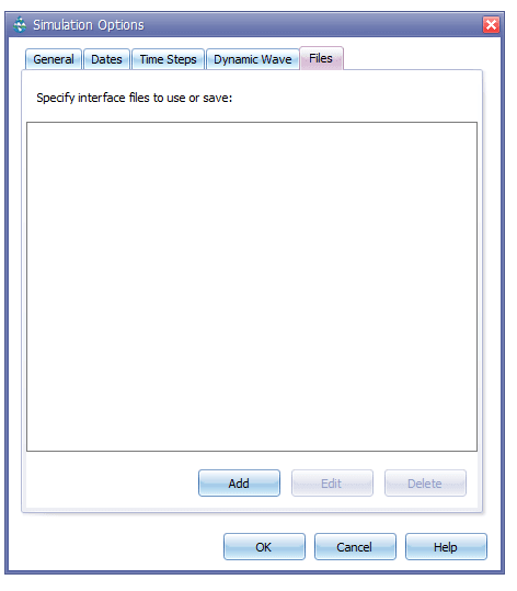
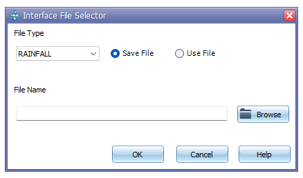
GeoSWMM can contain different kinds of Interface Files that contain either externally imposed inputs (e.g., rainfall or inflow/infiltration hydrographs) or the results of the previously outing analyses (e.g., runoff or routing results). These files can help speed up simulations, simplify comparisons of different loading scenarios, and allow large study areas to be broken up into smaller areas that can be analyzed individually. The interface file editing option has been provided under the Files tab in the Simulation Options setting window as shown in the following Figure 8.3. The user may add a new interface file or edit an existing interface file in a dialog box as shown in Figure 8.4. The different types of interface files that are currently available in this dialog box include:
- Rainfall Interface File
- Runoff Interface File
- Hot Start File
- RDII Interface File
- Routing Interface File.
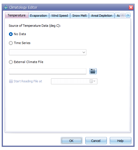
External Climate File
On the Temperature page (Figure 8.5) of the Climatology editor, the user can assign an external climate file that contains temperature, evaporation and wind velocity data in standard format. This is a time series file and GeoSWMM allows the user to incorporate the full dataset or only a particular portion of it (filtered by dates).
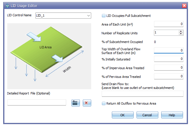
Detailed Report File of LID Usage Editor
GeoSWMM allows the user to manage the file in which the detailed time series results for the LID will be written. The entire time series of flux rates and moisture levels for the selected LID control in a given subcatchment is written in this file. The file name and directory can be assigned in the subcatchment LID Usage Editor window as shown in the following Figure 8.6.
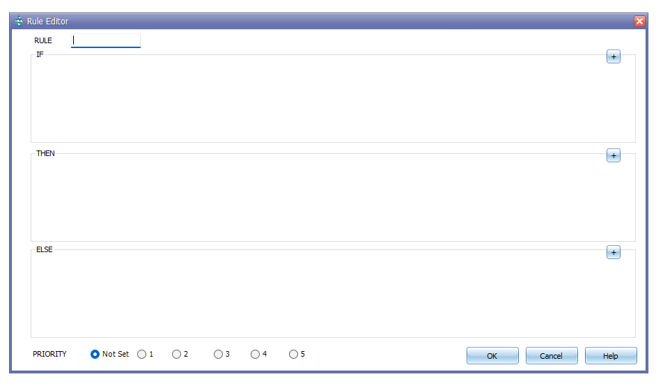
Control Rules
Control Rules determine how pumps and regulators in the conveyance system will be adjusted over the course of a simulation. Control rules can have an effect on any combination of velocity, flow and water level at nodes, conduits, pumps, weirs or orifices in the network. The application of control rules can be used on various hydro objects. The Control Rule Editor window in GeoSWMM looks like the following Figure 8.7.
Rule Format/Boolean logic structure (AND, OR, ELSE, PRIORITY)
Each control rule is a series of statements of the form:
RULE RuleID
IF condition_1
AND condition_2
OR condition_3
AND condition_4
etc.
THEN action_1
AND action_2
etc.
ELSE action_3
AND action_4
etc.
PRIORITY value
Where keywords are shown in boldface and ruleID is an ID label assigned to the rule, conditionn is a Condition Clause, actionn is an Action Clause, and value is a priority value (e.g., a number from 1 to 5). Each rule clause must begin with one of the boldface keywords shown above and only one clause per line is allowed. Only the RULE, IF and THEN portions of a rule are required; the ELSE and PRIORITY portions are optional. Blank lines between clauses are permitted and any text to the right of a semicolon is considered a comment.
When mixing AND and OR clauses, the OR operator has higher precedence than AND, such as:
IF A or B and C is equivalent to
IF (A or B) and C.
If the interpretation was meant to be
IF A or (B and C)
then it can be expressed using two rules as in
IF A THEN...
IF B and C THEN ...
The PRIORITY value is used to determine which rule applies when two or more rules require that conflicting actions be taken on a link. A rule without a priority value always has a lower priority than one with a value. For two rules with the same priority value, the rule that appears first is given the higher priority.
Condition Clause
A Condition Clause of a Control Rule has the following format.
object id attribute relation value
- Object (a category of object)
- Id (the object's ID label)
- Attribute (an attribute or property of the object)
- Relation (a relational operator (=, <>, <, <=, >, >=))
- Value (an attribute value)
Some examples of condition clauses are:
NODE J4 DEPTH > 8
PUMP P5 STATUS = ON
SIMULATION CLOCKTIME = 18:30:00
The objects and attributes that can appear in a condition clause are as follows:
Table 8.1 : List of Condition Clause Attributes
Object | Attributes | Value |
|---|---|---|
NODE | Depth | Numerical Value |
Head | Numerical Value | |
Inflow | Numerical Value | |
LINK | Flow | Numerical Value |
Depth | Numerical Value | |
PUMP | Status | ON Or OFF |
Setting | Pump Curve Multiplier | |
ORIFICE WEIR | Setting | Fraction Open |
OUTLET | Setting | Rating Curve Multiplier |
SIMULATION | Time | Elapsed Time In Decimal Hours or hr:min:sec |
Date | Month/Day/Year | |
Month | Month of Year (January - December). January = 1 | |
Day | Day of Week (Sunday - Saturday). Sunday = 1 | |
Clock time | Time Of Day in hr:min:sec |
Action Clause
An Action Clause of a Control Rule can have one of the following formats.
PUMP id STATUS = ON/OFF
PUMP/ORIFICE/WEIR/OUTLET id SETTING = value
The meaning of SETTING depends on the object being controlled:
- For Pumps, it is a multiplier applied to the flow computed from the pump curve
- For Orifices, it is the fractional amount that the orifice is fully open (orifice control is accomplished by lowering or raising a horizontal gate from the top of the orifice)
- For Weirs, it is the fractional amount of the original freeboard that exists (i.e., weir control is accomplished by moving the crest height up or down)
- For Outlets, it is a multiplier applied to the flow computed from the outlet's rating curve
Some examples of action clauses are:
PUMP P7 STATUS = OFF
ORIFICE O2 SETTING = 0.5
Pump on/off Control
RULE R3A
IF NODE N1 DEPTH > 5
THEN PUMP N1A STATUS = ON
RULE R3B
IF NODE N1 DEPTH > 7
THEN PUMP P1B STATUS = ON
RULE R3C
IF NODE N1 DEPTH <= 11
THEN PUMP P1A STATUS = OFF
AND PUMP P1B STATUS = OFF
Orifice Size Control
RULE R2A
IF NODE J2 DEPTH > 12
AND LINK C16 FLOW> 100
THEN ORIFICE R55 SETTING = 0.5
RULE R2B
IF NODE J13 DEPTH > 12
AND LINK C1FLOW> 200
THEN ORIFICE R55 SETTING = 1.0
RULE R2C
IF NODE J23 DEPTH <= 12
OR LINK C65 FLOW <= 100
THEN ORIFICE R55 SETTING = 0
Weir Crest Elevation Control
RULE R4
IF NODE N2 DEPTH >= 0
THEN WEIR W25 SETTING = CURVE C25
Simulation Time Based Rules
RULE R1
IF SIMULATION TIME > 8
THEN PUMP P8 STATUS = ON
ELSE PUMP P12 STATUS = OFF
Modulated controls
Modulated Controls are control rules that provide for a continuous degree of control applied to a pump or flow regulator as determined by the value of some controller variable, such as water depth at a node, or by time. The functional relation between the control setting and the controller variable can be specified by using a Control Curve, a Time Series, or a PID controller. Some examples of modulated control rules are:
RULE MC1
IF NODE N2 DEPTH >= 0
THEN WEIR W25 SETTING = CURVE C25
RULE MC2
IF SIMULATION TIME > 0
THEN PUMP P12 SETTING = TIMESERIES TS101
RULE MC3
IF LINK L33 FLOW <> 1.6
THEN ORIFICE O12 SETTING = PID 0.1 0.0 0.0
A modified form of the action clause is used to specify the name of the control curve, time series, or PID parameter set. that defines the degree of control. A PID parameter set contains three values: a proportional gain coefficient, an integral time (in minutes), and a derivative time (in minutes). Also, by convention the controller variable used in a Control Curve or PID Controller will always be the object and attribute named in the last condition clause of the rule. In rule MC1 above Curve, for example, C25 would define how the fractional setting at Weir W25 varied with the water depth at Node N2. In rule MC3, the PID controller adjusts the opening height of Orifice O12 to maintain a flow of 1.6 in Link L33.
Proportional Integral Derivative (PID) controllers
A PID (Proportional-Integral-Derivative) Controller is a generic closed-loop control scheme that tries to maintain a desired set-point on a process variable by computing and applying a corrective action that adjusts the process accordingly. In the context of a hydraulic conveyance system, a PID controller might be used to adjust the opening on a gated orifice to maintain a target flow rate in a specific conduit or to adjust a variable speed pump to maintain a desired depth in a storage unit. The classical PID controller has the form:
= controller output
= Proportional coefficient (gain)
= Integral time (minutes)
= Derivative time (minutes)
= Error (difference between set point and observed variable value)
= Time
The performance of a PID controller is determined by the values assigned to the coefficients .
The controller output has the same meaning as a link setting used in a rule's Action Clause while is the current flow routing time step in minutes. Because link settings are relative values (with respect to either a pump's standard operating curve or to the full opening height of an orifice or weir), the error used by the controller is also a relative value. It is defined as the difference between the control variable set point and its value at time t, , normalized to the set point value:
Note that for direct action control, where an increase in the link setting causes an increase in the controlled variable, the sign of must be positive. For reverse action control, where the controlled variable decreases as the link setting increases, the sign of must be negative. The user must recognize whether the control is direct or reverse action and use the proper sign on accordingly. For example, adjusting an orifice opening to maintain a desired downstream flow or downstream water level is direct action. Adjusting it to maintain an upstream water level is reverse action. Controlling a pump to maintain a fixed wet well water level would be reverse action while using it to maintain a fixed downstream flow is direct action.
Curve Editor
Curve objects are used to describe a functional relationship between two parameters. The following types of curves are available in GeoSWMM:
- Storage curve describes how the surface area of a Storage Unit node varies with water depth.
- Shape curve describes how the width of a cross-sectional shape varies with height for a Conduit link.
- Diversion curve relates diverted outflow to total inflow for a Flow Divider node.
- Tidal curve describes how the stage at an Outfall node changes by hour of the day.
- Pump curve relates flow through a Pump link to the depth or volume at the upstream node or to the head delivered by the pump (Figure 8.8).
- Rating curve relates flow through an Outlet link to the freeboard depth or head difference across the outlet.
- Control curve determines how the control setting of a pump or flow regulator varies as a function of some control variable as specified in a Modulated Control rule.

GeoSWMM enables the user to utilize different formats of data such as text, CSV, PRN etc. for import and use in the curve editor.
Time Series Import
Similar to the EPA-SWMM, the user can set an external time series file in the time series editor in GeoSWMM. However, in GeoSWMM, an advanced option is provided to import data directly into the time series data entry table. The Import button in the time series editor opens a new window where the user will need to browse directory and select the file name. The editor recognizes the data structure in the file based on the format specified by the user (Figure 8.9). A sample data format for this file has been provided in Appendix E.5.
Export Input File for EPA SWMM 5.1
GeoSWMM can export the model input file for EPA-SWMM 5.1. It accurately preserves all the model parameters in the input file. In addition, GeoSWMM keeps the information of the spatial reference of the model geodatabase layers in the file that could be useful. The user can see the information by opening the input file in a text editor. The spatial reference is the key information required for model development in ArcGIS Pro environment and spatial analysis. It enables users to develop a SWMM model in ArcGIS Pro from the input file in future. A sample SWMM input file generated by GeoSWMM has been provided in Appendix E.6.
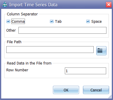
Calibration Data Series Import
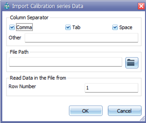
Users can import an external calibration data series file through the Calibration Data Manager in GeoSWMM. However, GeoSWMM also provides an advanced import option that allows users to import data directly into the Calibration Data Manager table. Clicking the Import button opens the calibration data import window (Fig. 2). In this window, users can browse directories, select the desired data file, and specify how the data should be interpreted. The importer automatically reads the file based on the selected format and delimiter options.
Key Settings:
- Column Separator: Choose how data fields are separated — Comma, Tab, or Space. Users can also define a custom separator under Other.
- File Path: Browse to locate the calibration data file to be imported.
- Read Data in the File from Row Number: Specify the first row of data to be read (default is 1).
Once all settings are configured, click OK to import the data or Cancel to close the dialog. A sample data format for this file has been provided in Appendix E.7.