Subcatchment Characteristic Width Calculation
The "Subcatchment Characteristic Width Calculation" tool helps GeoSWMM users estimate the characteristic width property for the model subcatchments. It primarily works with a subcatchment layer and a conduit layer (or stream layer) to measure the characteristic width. However, this is a calibration parameter, and the tool only provides the best approximation of width value based on the user inputs. The tool stores the calculated widths in an attribute field of the subcatchment layer.
Width Estimation Principles
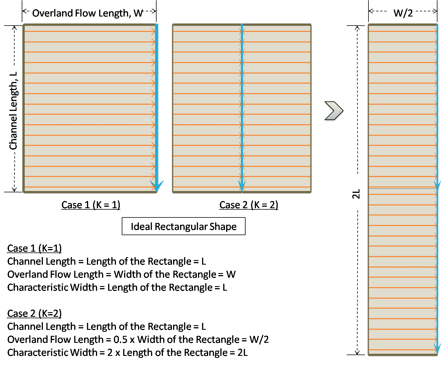
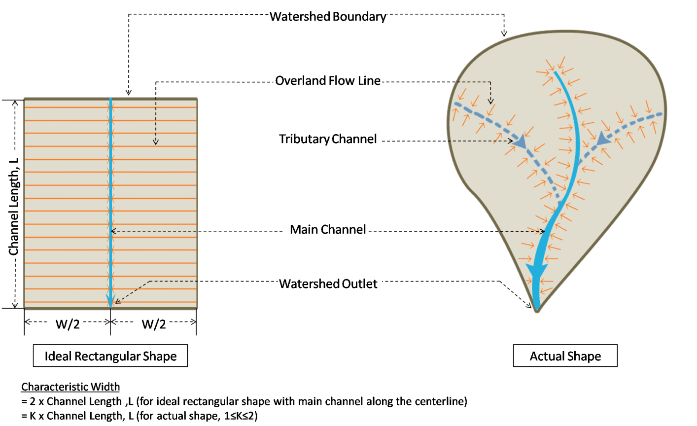
The characteristic width is a special hydrologic parameter for a subcatchment that affects the time of concentration and determines the shape of the runoff hydrograph. It depends on the characteristics of the overland flow length and the shape of the subcatchment. If the overland flow line is represented by the physical width of an ideal rectangular shaped subcatchment, then the characteristic width will be the physical length of that rectangle (Figure 6.34). However, in reality, subcatchments are shaped like non-uniform polygons and therefore the width cannot be estimated in a straightforward manner (Figure 6.35). It is one of the key calibration parameters in a SWMM model because it can significantly alter the runoff hydrograph properties. The user needs to have a proper understanding of the basin characteristics and the overland flow behavior when estimating subcatchment width.
The characteristic width can be estimated in the tool using all of the following methods. However, there are some other empirical techniques also applied in several hydrologic modeling applications.
Subcatchment Characteristic Width is the maximum of: = K × Channel Length, and = Subcatchment Area / (K×Maximum Overland Flow Length) | ...(6.1) |
|---|
or
Subcatchment Characteristic Width =Subcatchment Area/Channel Length | ...(6.2) |
|---|
Here K is a skew or length adjustment factor () that accounts for the shape of the subcatchment. The channel length is computed from the intersected conduit layer over the subcatchment layer while estimating the subcatchment width. However, the tool provides an advanced option to adjust the channel lengths for the head-watersheds. Head-watersheds are the furthest upstream subcatchments in a SWMM model that initiate the stream formation. Sometimes the length of the delineated streamline in a head-watershed is too small and does not accurately represent the actual flow path length. In such case, further adjustment is required to estimate the correct value of the subcatchment width, especially for those head-watersheds. The best solution might be to use the longest flow path length for these head-watersheds. However, the user is responsible for precise estimation of effective channel length for these head-watersheds during width calculation.
In this aspect, the tool allows a user to calculate the longest flow path length for the head-watersheds using a DEM raster data. Then the user can assign the longest flow path lengths in the computation of subcatchment width. The tool also allows the user to manually adjust the channel lengths of the head-watersheds.
A good estimate for the width can be obtained by determining the average maximum length of overland flow and dividing the area by this length. When assigning an overland flow path length, particularly for sites with natural land cover, one must recognize that there is a maximum distance over which true sheet flow prevails. Beyond this, runoff consolidates into rivulet flow with much faster travel times and less opportunity for infiltration. There is no general agreement on what distance should be used as a maximum overland flow path length. The Natural Resources Conservation Service recommends a maximum length of 100 ft (NRCS, 2010) while Denver’s Urban Drainage and Flood Control District uses a maximum of 500 ft. (UDFCD, 2007).
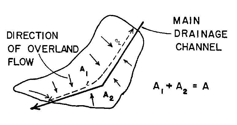
Another estimate for the width is twice the length of the main drainage channel. However, this estimate assumes approximately equal areas on both sides of the drainage channel whereas most real subcatchments irregular in shape and have a drainage channel that is off center, as shown in Figure 6.36. This is especially true of rural or undeveloped watersheds. A simple way of handling this case is given by DiGiano et al. (1977). A skew factor may be computed,
… (6.3) |
|---|
Where,
Z = skew factor, 0.5 ≤ Z ≤ 1
Am = larger of the two areas on each side of the channel
A = total area.
If L is the length of the main drainage channel, then the width W is simply weighted sum between the two limits of L and 2L:
… (6.4) |
|---|
A more fundamental approach to estimating both subcatchment width and slope has recently been developed by Guo and Urbonas (2007). The idea is to use “shape factors” to convert a natural irregular watershed as pictured in Fig 100 into an idealized overland flow plane. A shape factor is an index that reflects how overland flows are collected in a watershed. The shape factor X for the actual watershed is defined as where A is the watershed area and L is the length of the watershed’s main drainage channel (not necessarily the length of overland flow). The shape factor Y for the idealized watershed is . Requiring that the areas of the actual and idealized watersheds be the same and that the potential energy in terms of the vertical fall along the drainage channel be preserved, Guo and Urbonas (2007) derive the following expression for the shape factor Y of the idealized watershed:
… (6.5) |
|---|
Where, K is an upper limit on the watershed shape factor. Guo and Urbonas (2007) recommend that K be between 4 and 6 and note that a value of 4 is used by Denver’s Urban Drainage and Flood Control District. Once Y is determined, the equivalent width W for the idealized watershed is computed as .
Working with the Width Tool
GeoSWMM provides three methods for width calculation:
- Area and Overland Flow Length ratio method
- DiGiano Method
- Guo and Urbonas Method
Area/ Over Land Flow Length
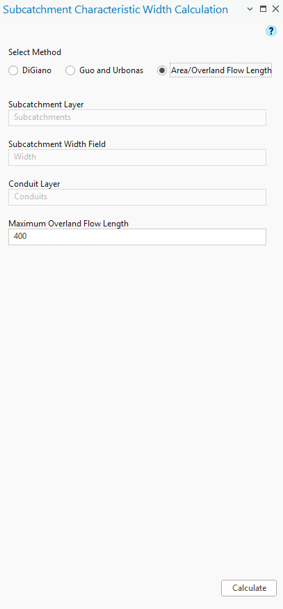
The Subcatchment Characteristic Width Calculation tool primarily has three compartments in the interface that looks like the following Figure 6.37. The first portion contains the user inputs. The next portion allows the user to adjust the channel lengths of the head-watersheds. The third and final section executes width calculation following a method specified by the user from a drop-down list. The input parameters for the width calculation are described in following.
Method
It shows the available methods that can be used to calculate the width of the subcatchment.
Subcatchment Layer
This is a polygon feature layer that represents the model subcatchments.
Subcatchment Width Field
This is an attribute field available in the subcatchment layer where the tool will store the calculated width values. However, if a new field name is assigned, then the tool will create it in the attribute table.
Maximum Overland Flow Length
It represents the maximum length of the overland water flow. The user input depends on the choice for the width calculation method. The default value is set to 400 in the map unit.
The calculation steps involved in the estimation of the subcatchment characteristic width are described in the following points.
The subcatchment layer and the conduit layer are the primary inputs required for width calculation. These layers must be present in the TOC of ArcGIS Pro map before launching width calculation tool. These layers must have the same projected coordinate system in order to accurately perform the width calculation.
The tool window (Fig. 6.37) can be opened by clicking on the Width calculation (![]() ) button from the GeoSWMM Tools.
) button from the GeoSWMM Tools.
Then the user will need to specify the required inputs such as the subcatchment layer, subcatchment width field, and maximum overland flow length.
The method estimates the subcatchment width based on the user specified values of the overland flow length.
Finally, clicking on the Calculate button will execute the computations for the subcatchment characteristic width and assign the results in the user assigned field in the respective subcatchment layer.
DiGiano Method
The Subcatchment Characteristic Width Calculation tool primarily has three compartments in the interface that looks like the following Figure 6.38. The first portion contains the user inputs. The next portion allows the user to adjust the channel lengths of the head-watersheds. The third and final section executes width calculation following a method specified by the user from a drop-down list. The input parameters for the width calculation are described in following.
Method
It shows the available methods that can be used to calculate the width of the subcatchment.
Subcatchment Layer
This is a polygon feature layer that represents the model subcatchments.
Subcatchment Width Field
This is an attribute field available in the subcatchment layer where the tool will store the calculated width values. However, if a new field name is assigned, then the tool will create it in the attribute table.
Conduit Layer
This is a polyline feature layer that represents the model conduits (both open channel and closed conduits).
Input DEM
This is raster data representing the surface elevation. This input is required only to calculate the longest flow path length.
The calculation steps involved in the estimation of the subcatchment characteristic width are described in the following points.
The subcatchment layer and the conduit layer are the primary inputs required for width calculation. These layers must be present in the TOC of ArcGIS Pro map before launching width calculation tool. These layers must have the same projected coordinate system in order to accurately perform the width calculation.
The tool window (Figure 6.38) can be opened by clicking on the Width calculation (![]() ) button from the GeoSWMM Tools.
) button from the GeoSWMM Tools.
Then the user will need to specify the required inputs such as the subcatchment layer, subcatchment width field, and the conduit layer.
Checking the Adjust Head-watershed Channel Length option will enable users to edit the conduit lengths of the head-watersheds before performing the width calculation. There are two options provided (Use Channel length and Use Longest Flow Length) for adjusting the head-watershed channel lengths as shown in the following Fig.6.39. The Use Channel Length option allows the user to edit the actual conduit length values in a table. On the other hand, the Use Longest Flow Length option allows the user to calculate the longest flow lengths for the head-watersheds using a DEM raster and assign them for the width calculation.
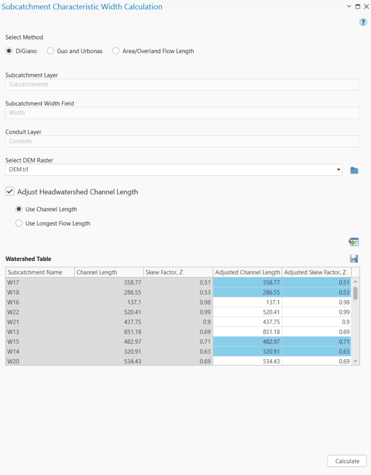
The Generate Head-watershed Table button processes the channel lengths for the head-watersheds and displays them in a table (Figure 6.39). The fields shown in this table are the Subcatchment Name , Calculated channel length (actual channel length or the longest flow length),Skew Factor, Adjusted Channel Length and Adjusted Skew Factor .The user can edit the channel lengths only in the Adjusted Channel length field, which will subsequently be used in the width calculation. The first three columns will be non-editable .
Finally, clicking on the Calculate button will execute the computations for the subcatchment characteristic width and assign the results in the user assigned field in the respective subcatchment layer.
Guo and Urbonas Method
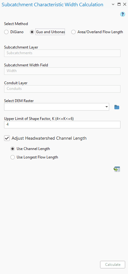
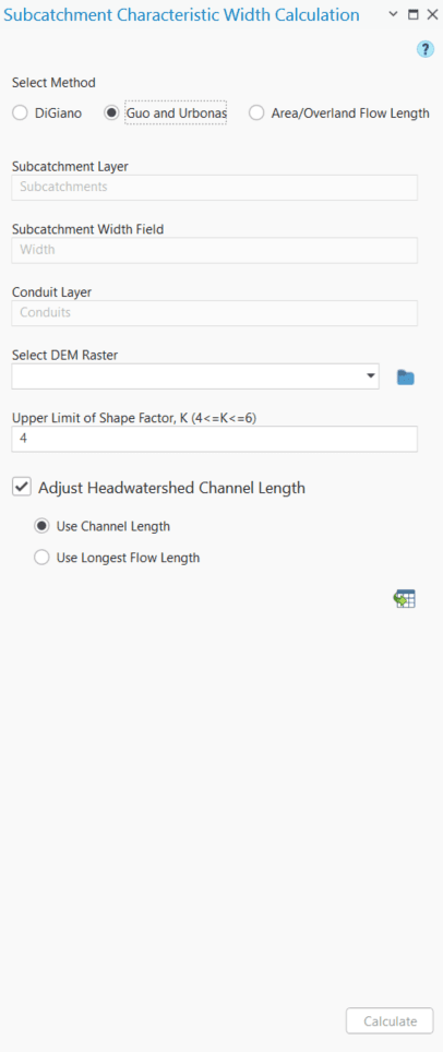
The Subcatchment Characteristic Width Calculation tool primarily has three compartments in the interface that looks like the following Figure 6.40. The first portion contains the user inputs. The next portion allows the user to adjust the channel lengths of the head-watersheds. The third and final section executes width calculation following a method specified by the user from a drop-down list. The input parameters for the width calculation are described in following.
Method
It shows the available methods that can be used to calculate the width of the subcatchment.
Subcatchment Layer
This is a polygon feature layer that represents the model subcatchments.
Subcatchment Width Field
This is an attribute field available in the subcatchment layer where the tool will store the calculated width values. However, if a new field name is assigned, then the tool will create it in the attribute table.
Conduit Layer
This is a polyline feature layer that represents the model conduits (both open channel and closed conduits).
Input DEM (Optional)
This is raster data representing the surface elevation. This input is required only to calculate the longest flow path length.
Upper Limit of Shape Factor, K
K is the skew factor that accounts for the change in subcatchment characteristic width due to the non-uniform shape of the subcatchment. The user input depends on the choice of the width calculation method. The default value is set to 4 (4 ≤ K ≤ 6).
The calculation steps involved in the estimation of the subcatchment characteristic width are described in the following points.
The subcatchment layer and the conduit layer are the primary inputs required for width calculation. These layers must be present in the TOC of ArcGIS Pro map before launching width calculation tool. These layers must have the same projected coordinate system to accurately perform the width calculation.
The tool window (Figure 6.40) can be opened by clicking on the Width calculation (![]() ) button from the GeoSWMM Tools.
) button from the GeoSWMM Tools.
Then the user will need to specify the required inputs such as the subcatchment layer, subcatchment width field, and the conduit layer.
Checking the Adjust Head-watershed Channel Length option will enable users to edit the conduit lengths of the head-watersheds before performing the width calculation. There are two options provided (Use Channel length and Use Longest Flow Length) for adjusting the head-watershed channel lengths as shown in the following Figure 6.41. The Use Channel Length option allows the user to edit the actual conduit length values in a table. On the other hand, the Use Longest Flow Length option allows the user to calculate the longest flow lengths for the head-watersheds using a DEM raster and assign them for the width calculation.
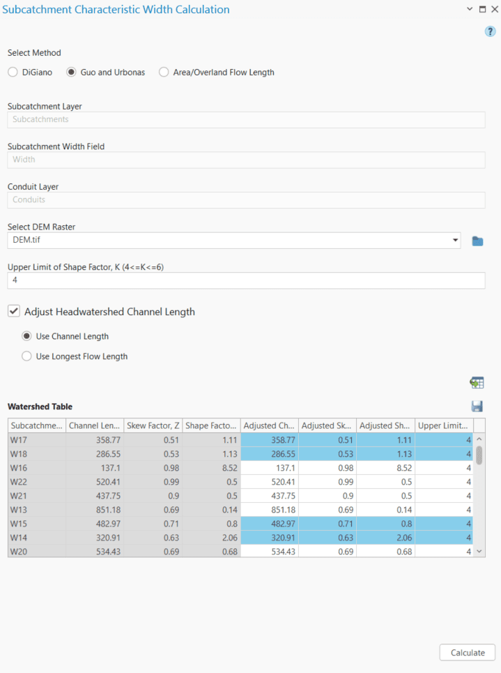
The Generate Head-watershed Table button processes the channel lengths for the head-watersheds and displays them in a table (Figure 6.41). The fields shown in this table are the Subcatchment Name, Calculated channel length (actual channel length or the longest flow length), Skew Factor, Adjusted Channel Length and Adjusted Skew Factor. The user can edit the channel lengths only in the Adjusted Channel length field, which will subsequently be used in the width calculation. The first three column will be non-editableFinally, clicking on the Calculate button will execute the computations for the subcatchment characteristic width and assign the results in the user assigned field in the respective subcatchment layer.