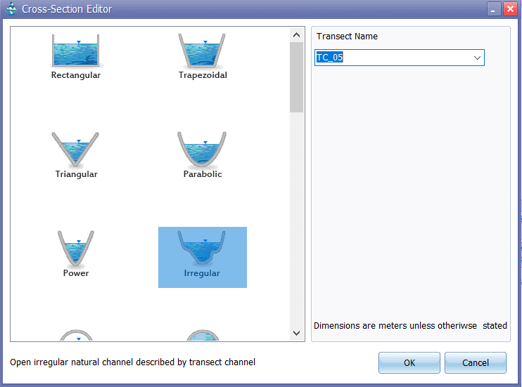
C.3 Cross-Section Editor
The Cross-Section Editor dialog is used to specify the shape and dimensions of a conduit's cross- section. When a shape is selected from the dropdown combo box an appropriate set of edit fields appears for describing the dimensions of that shape. Length dimensions are in units of feet for US units and meters for SI units. Slope values represent ratios of horizontal to vertical distance. The Barrels field specifies how many identical parallel conduits exist between its end nodes.

If an Irregular shaped section is chosen, a drop-down edit box will appear where the user can enter or select the name of a Transect object that describes the cross-section's geometry.
The Force Main shape option is a circular conduit that uses either the Hazen-Williams or Darcy- Weisbach formulas to compute friction losses for pressurized flow during Dynamic Wave flow routing. In this case the appropriate C-factor (for Hazen-Williams) or roughness height (for Darcy- Weisbach) is supplied as a cross-section property. The choice of friction loss equation is made on the Dynamic Wave Simulation Options dialog. Note that a conduit does not have to be assigned a Force Main shape for it to pressurize. Any of the other closed cross-section shapes can potentially pressurize and thus function as force mains using the Manning equation to compute friction losses.
