GeoSWMM
The GeoSWMM model, a geospatial stormwater and wastewater management model, has been developed as an add-in to ESRI's ArcGIS Pro 3.4.1 and later versions. It is a dynamic rainfall-runoff simulation modeling tool for a single event or long-term (continuous) simulation of runoff quantity and quality from primarily urban areas. The runoff component of GeoSWMM operates on a collection of sub catchment areas that receive precipitation and generates runoff and pollutant loads. The routing portion of GeoSWMM transports this runoff through a system of pipes, channels, storage/treatment devices, pumps, and regulators. This tool tracks the quantity and quality of runoff generated within each sub catchment and the flow rate, flow depth, and quality of water in each pipe and channel at each simulation time step.
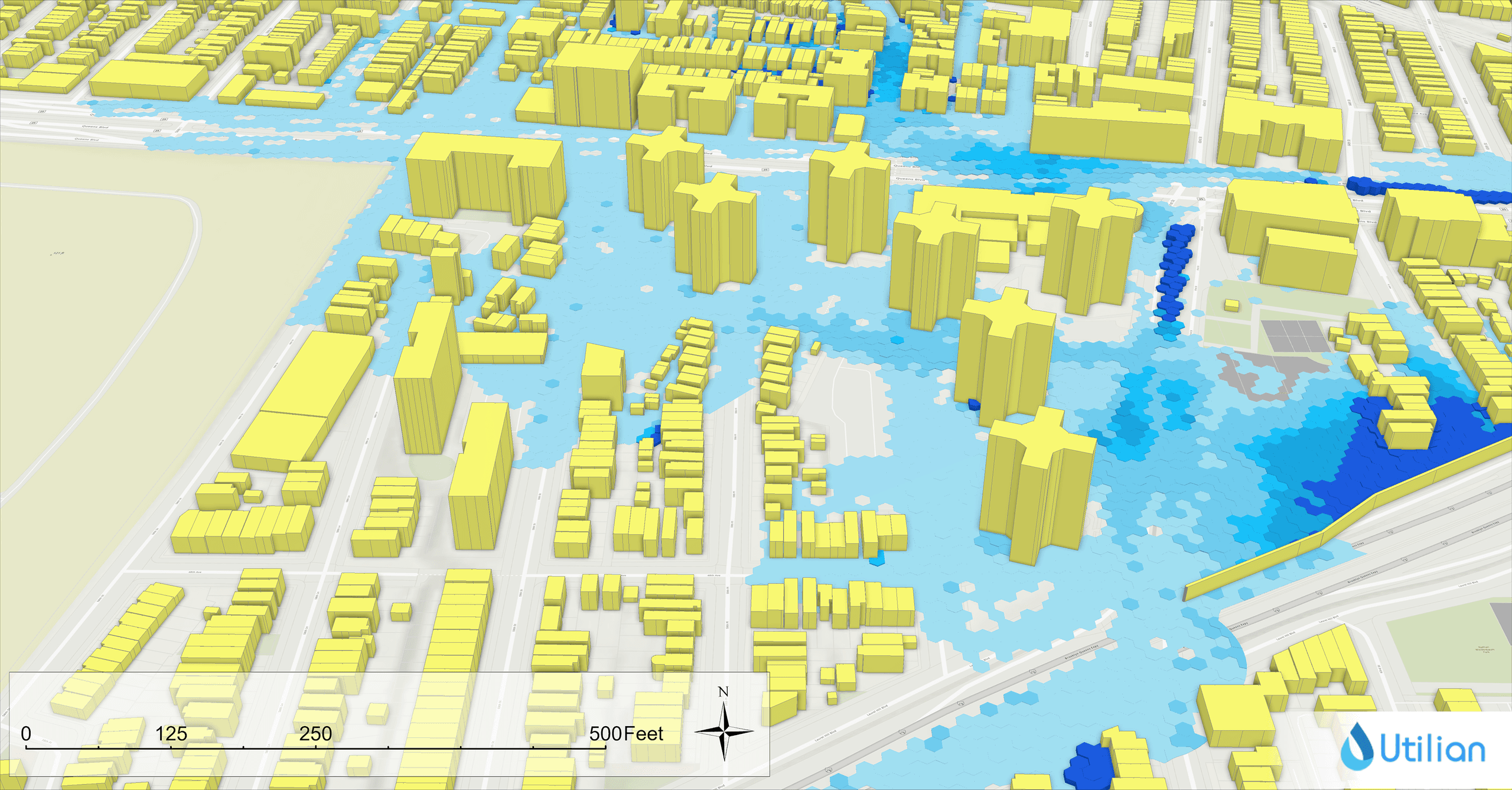
By allowing users to prepare model input and run the model within ArcGIS Pro, GeoSWMM provides users access to all ArcGIS Pro functions and tools to create and edit data. Users can take advantage of GeoSWMM and any other tools in the Geographic Information System (GIS) environment for planning, analysis and design of stormwater runoff, storm sewer, combined sewers, sanitary sewers, and other drainage systems in urban areas, with many applications in non-urban settings as well. It also provides an integrated environment for editing study area input data, running hydrologic, hydraulic and water quality simulations and viewing the results in a variety of formats. These include color-coded drainage area and conveyance system maps, time series graphs and tables and profile plots. All these features and functions can be accessed within the GIS environment.

.png&w=2560&q=75&dpl=dpl_HMofHTFhdz3TtVpQbDnmBr4xhpBT)
